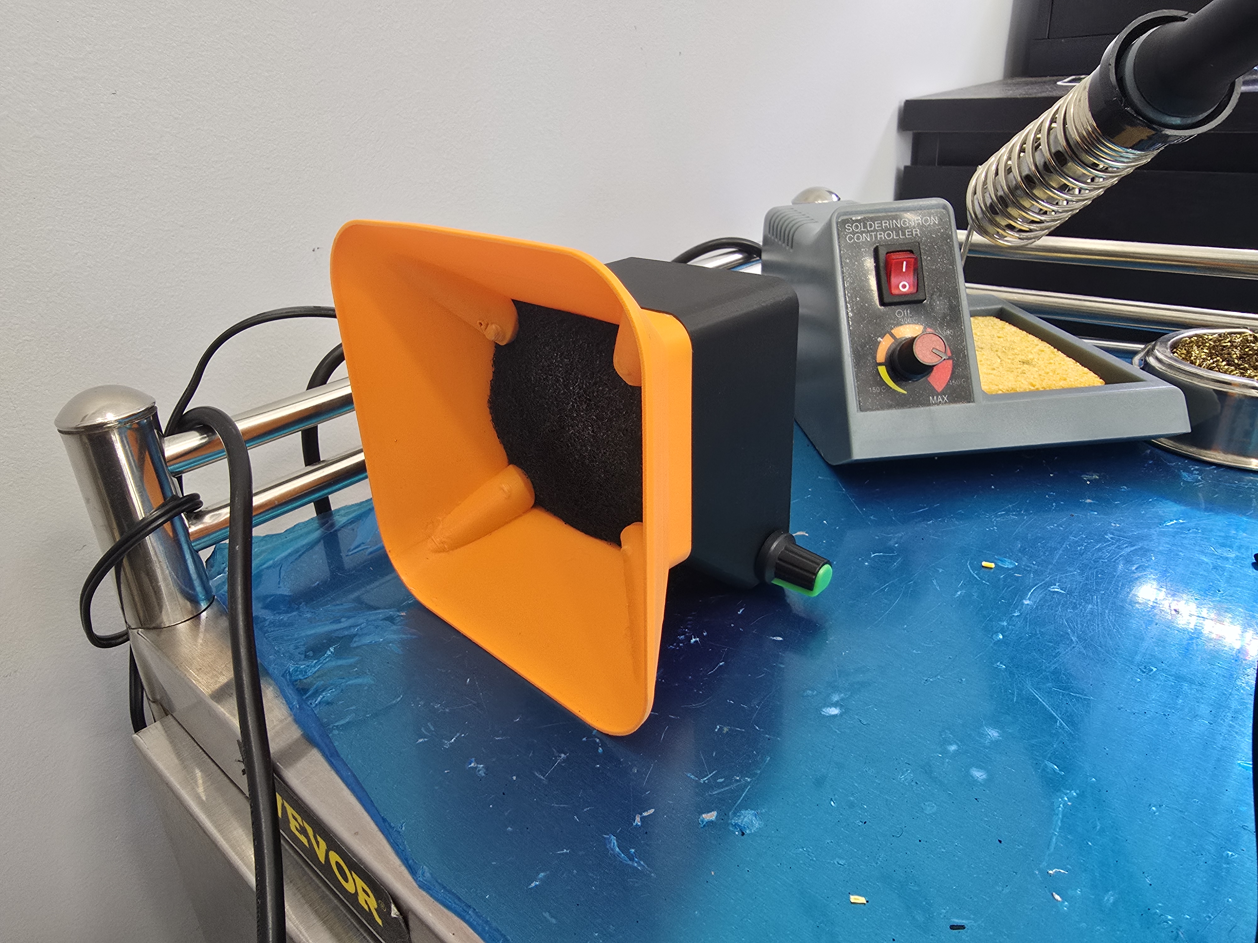
DIY Solder Station Vent
I've been planning more soldering projects and wanted to make a solder vent extractor; it needed to be more than just a fan and powerful enough to really suck the fumes.
I found this model on MarkWorld using a 60x60x40mm server fan:
Tabletop solder fume extractor by flummerMakerWorld: Download Free 3D Models
I liked the idea and form-factor, but having worked with servers before I know how loud these little fans can get, and wanted to add a speed controller.
So I started the print and ordered the following parts from Amazon:
tl;dr
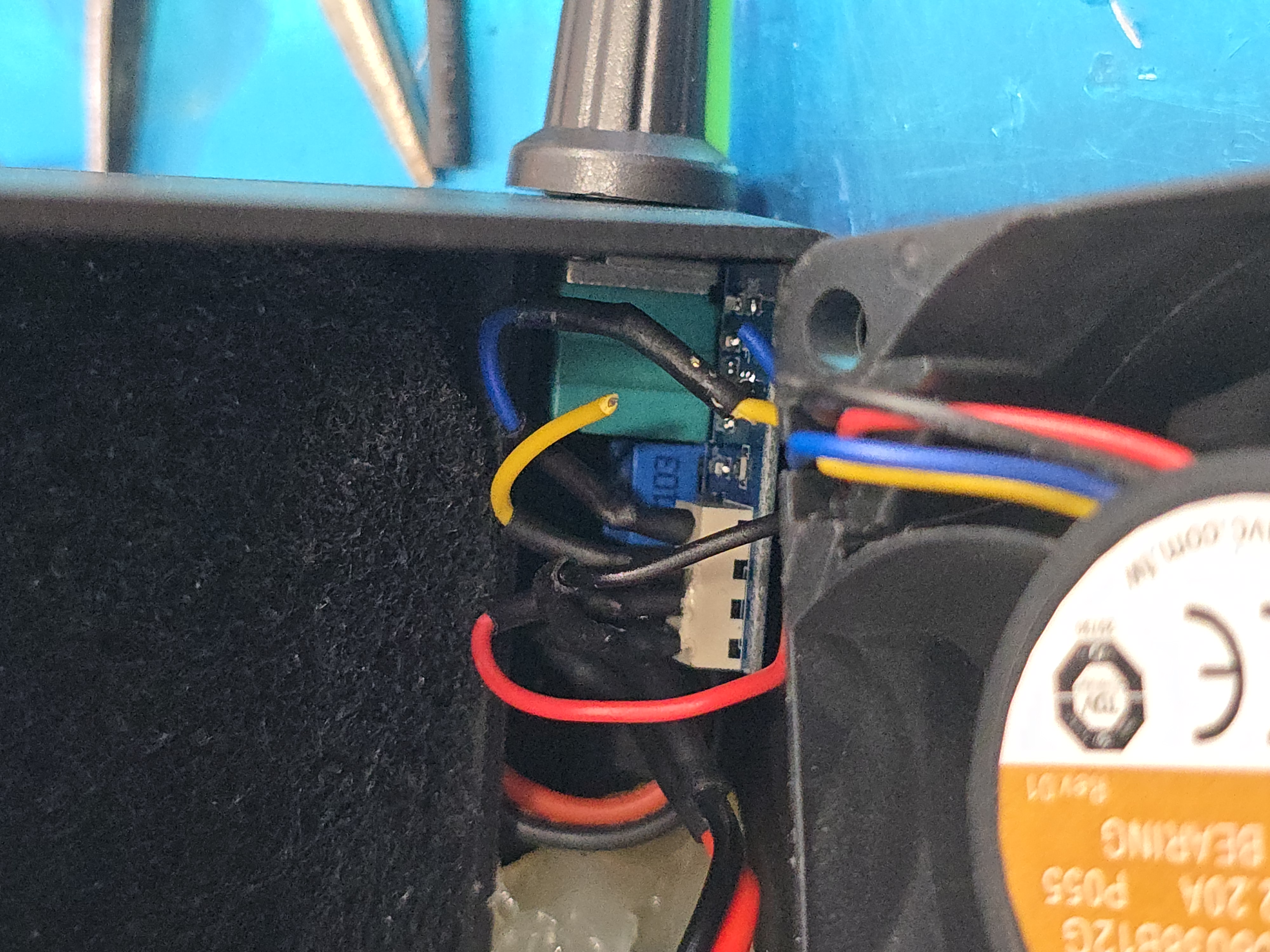
- Fan PWM wiring is backwards; yellow is PWM and blue is speed control/tach.
- Assembling the fan with the filters behind the fan cause backdraft issues; filters in front more cleanly draw the air through.
The project itself is not that complicated or interesting, and I just wanted to call out a few things for anyone else who wants to do this kind of project and doesn't have the information at-hand.
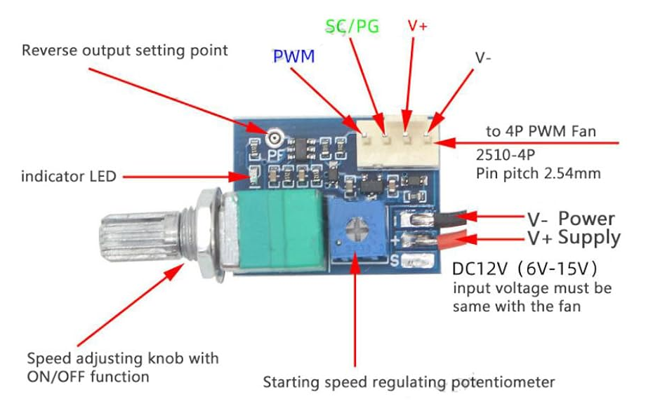
The fan speed controller has four pins you can connect to; Neutral, Positive, "SC/PG", and "PWM." If you're not familiar, PWM stands for "Pulse Width Modulation," and SC stands for "Speed control"[1] (also commonly known as a tachometer) and is how the fan speed is communicated back to the CPU, and we don't need it here.
The fan has 4 wires on it; Red, Black, Blue, and Yellow.
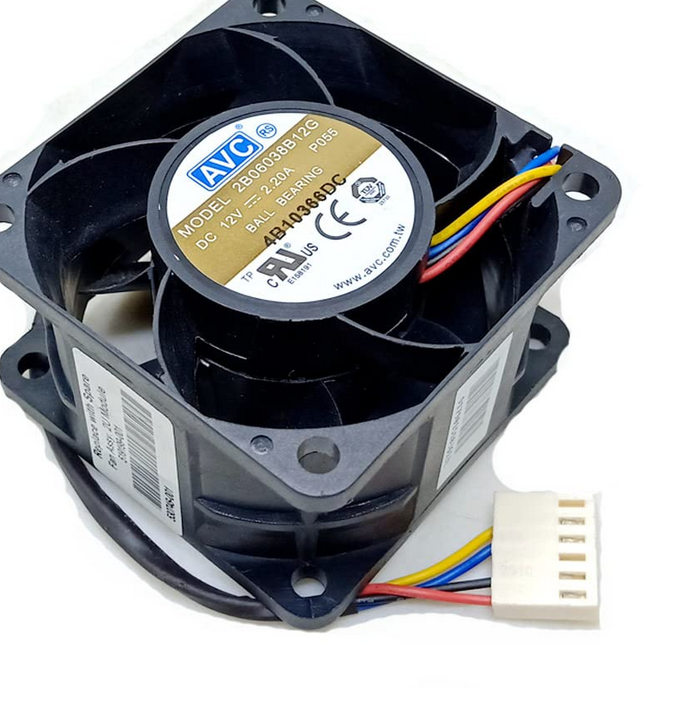
Black (neutral) and Red (positive) were clear, but I wasn't sure about the Blue and Yellow wires. I did some looking around and found some guides that indicated that Blue was PWM and yellow was for the tachometer.[2]
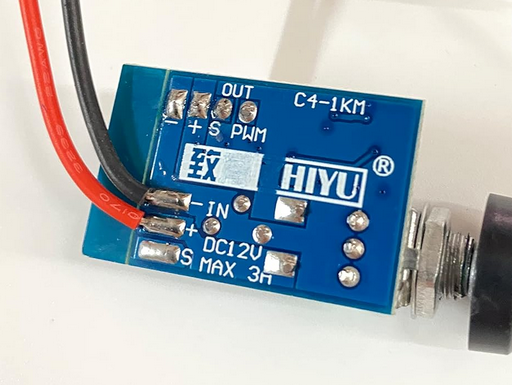
Anyway, these are reversed for this fan and I only tested it after I applied the heat shrink and assembled everything, so I had to go back in later and cut/resolder the cables. The whole thing is a bit of a mess, but it works, and that's what theoretically matters.
I probably should have removed the whole connector for more space and removed the unnecessary wires, but I just trimmed the connectors and plastic alignment tab and called it a day.
Speaking of assembly, I noticed that the picture on MakerWorld had the carbon filters on the back.
In testing, I found this "Push" configuration created tons of backdrafting coming out the front; basically air escaping around the fan blades and out the front, blowing some unfiltered air back in my face!
So I put the filters in the very front, used a screw driver to tap the filters away from the fan blades, and now fumes get sucked through the filter first and then out the back of the fan, and I control how effective or painfully loud it is.